LoRa Network Setup
Each LR200 LoRa converter consists of one main board and one LoRa board
| Model | Description | Main board | LoRa board |
| LR200EM | Modbus TCP to RTU over LoRa | Ethernet to UART | UART to LoRa |
| LR200E | Ethernet to LoRa | Ethernet to UART | UART to LoRa |
| LR200S | Serial to LoRa | RS232/485/422 to UART | UART to LoRa |
| LR200U | Serial (USB VCOM) to LoRa | USB to UART | UART to LoRa |
| LR200DM | Modbus RTU DIO over LoRa | Digital I/O | UART (RTU) to LoRa |
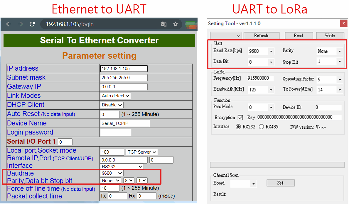
Both LoRa board and Ethernet board contain serial parameter settings such as 9600/N/8/1. These serial parameter settings of both boards must be the same so both boards can communicate with each other.
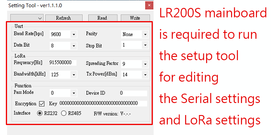
The LoRa board must be installed on the LR200S main board and connected to the computer via RS232 or RS485. Then run the LoRa setup program to set up the LoRa board. Refer to document for details of LoRa board setup.
Log in to the LoRa converter via the browser webpage to configure the Ethernet board.
LoRa Network Grouping
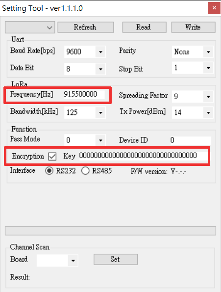
LR200 LoRa converters with the same frequency and encryption key will be grouped as the same LoRa network when they are powered on.
LoRa works like a wireless half duplex RS485. Only one master can broadcast to other slaves in the same LoRa network, and the slave with the corresponding ID will respond to the broadcasing.
The frequency between any two different LoRa networks must differ by at least 0.5 MHz to avoid interference with each other. Assume there are 3 different LoRa networks, each LoRa network frequency can be, for example, 915.5 MHz, 916 MHz, and 916.5 MHz.
LoRa Data Rate Configuration
Three parameters can be adjusted: TX power, bandwidth and spreading factor. If you lower the TX power, you’ll save battery, but the range of the signal will obviously be shorter. The other two parameters combined form the data rate. This determines how fast bytes are transmitted. If you increase the data rate (make the bandwidth wider or the spreading factor lower) you can transmit those bytes in a shorter time. For those, the calculation is approximately as follows: Making the bandwidth 2x wider (from BW125 to BW250) allows you to send 2x more bytes in the same time. Making the spreading factor 1 step lower (from SF10 to SF9) allows you to send 2x more bytes in the same time. Lowering the spreading factor makes it more difficult for the gateway to receive a transmission, as it will be more sensitive to noise. You could compare this to two people taking in a noisy place (a bar for example). If you’re far from each other, you have to talk slow (SF10), but if you’re close, you can talk faster (SF7)
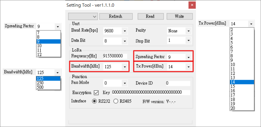
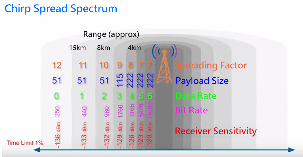
Above Spread Spectrum is for reference only